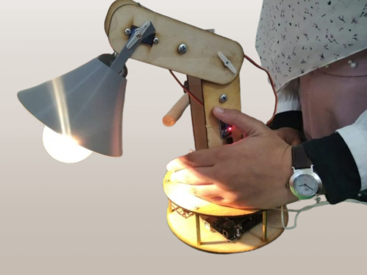
Do you want to create your own customizable, automated disk lamp? With the increasing popularity of smart home devices, making your own internet-connected lamp with customizable features like motion sensing and adjustable brightness can be an enjoyable electronics project. This article will provide a step-by-step guide to making your own smart disk lamp.
Supplies Needed
To create your own smart disk lamp, you will need the following supplies:
- Arduino UNO
- Breadboard
- Wires
- Ultrasonic sensor
- LDR (Light Dependent Resistor)
- Relay
- Bulb
- Screw cap
- Potentiometers
- Servo motors
- Electrical plug
- Adapter (6V)
- Spacers
- Fusion 360 (CAD Software)
- Arduino programming software
- Tinkercad (optional)
- Drill
- Laser Cutting Machine
- 3D Printer
- Screwdriver
These supplies are essential for testing the circuit, designing the lamp using CAD software, fabricating the lamp with laser cutting and 3D printing, assembling the lamp, and coding its functionality. Make sure to gather these supplies before starting the project.
Step 1: Test the Circuit
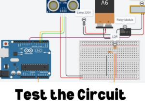
Testing the circuit is the first thing you need to do when making your own smart disc lamp. Before continuing with the rest of the project, it is important to check that all of the individual components are functioning as expected.
After you have successfully connected the Arduino to the breadboard, proceed to mount the LDR, ultrasonic sensor, and potentiometers on the proper pins of the Arduino. Servo motors should be attached, and the appropriate connections should be made.
When everything is in place, it is time to test the circuit and make sure that all of the components are operating as they should be doing their jobs.
Step 2: CAD Design

After you have verified that all of the components are operating as expected and tested the circuit, it is time to proceed to the next phase, which is the design of the circuit using CAD software. CAD software, also known as computer-aided design, gives you the ability to develop a digital model of your smart disc lamp before you begin the process of constructing it.
You are able to design the bases, arms, and other components of the lamp by making use of features and tools such as Sketch, Offset, Projection, Extrude, Revolve Joints, and Fillet.
This phase is extremely important since it will determine whether or not your design is exact and whether or not it will fit together correctly when it is fabricated. Therefore, fire up your CAD software and let your imagination run wild!
Step 3: Fabrication
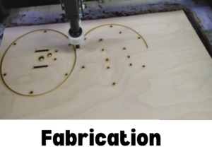
After you have finished designing your smart disc light using CAD software, it is time to move on to the step of fabricating the lamp. To bring your lamp to life, you will need to assemble all of the required components, using the design as a guide.
This includes the materials and tools. It’s possible that the bases and arms will need to be cut with a laser for this step, as well as any other components that are required. During the manufacturing process, you should take your time to ensure that the product is precise and accurate because this will influence the overall quality of your smart disc lamp.
After you have cut out everything and printed everything you need, you may move on to the next stage, which is assembly.
Step 4: Assemble
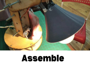
Now that you have completed the fabrication of your smart disk lamp, it’s time to assemble all the components. Start by aligning the bases and arms according to your CAD design. Attach the 3D printed parts and secure them with screws or spacers. Connect the Arduino, relay, ultrasonic, and servo motors as per your circuit diagram. Take your time to ensure everything is properly connected and secure. Once all the components are assembled, you can move on to the next step: coding.
Step 5: Coding
After you have finished the manufacturing step of your smart disc lamp, it is time to move on to the coding portion of the project. Get started by assembling all of the required software and hardware, such as the Tinkercad and Arduino programming software.
#include <Servo.h>
Servo myservo2;

int potpin2 = 0;
int val2;

Servo myservo;

int potpin = 0;
int val;
int ldr = 4;
int bulb = 3;
int trig = 5;
int echo = 2;
void setup() {
  myservo2.attach(11);
  myservo.attach(9);
  pinMode (ldr, INPUT );
  pinMode (bulb, OUTPUT);
  pinMode (trig , OUTPUT);
  pinMode (echo ,INPUT );
  Serial.begin(9600);
}
void loop() {
  long duration, cm;
  digitalWrite(bulb, LOW);
  delayMicroseconds(echo);
  digitalWrite(bulb, HIGH);
  delayMicroseconds(trig);
  digitalWrite(bulb, LOW);
  duration = pulseIn(echo, HIGH);
  cm = duration/29/2;
  Serial.print(cm);
  Serial.print("cm");
  Serial.println();
  delay(100);
  int motion ;
  if (cm < 30) {
    motion =1 ;
  } else {
    motion =0;
  }
  int brightness = digitalRead (ldr);
  if (motion){
  if (brightness) {
    digitalWrite (bulb, HIGH);
  }
  else {
        digitalWrite (bulb, LOW);
  }
  Serial.print(brightness);
  Serial.print(",");

  }
  else {
    digitalWrite( bulb, LOW );
  }
  val = analogRead(potpin);
  Serial.println(map(val, 0, 1023, 0, 180) );
  val = map(val, 0, 1023, 0, 180);
  myservo.write(val);
  val2 = analogRead(potpin2);
  val2 = map(val2, 0, 1023, 0, 180);
  myservo2.write(val2);
  delay(15);


}
Establish a connection between your breadboard and Arduino, then start creating the code for your lamp. The functionality of your lamp, including its reaction to motion and the amount of light present, will be determined by this code. Invest some time and effort into learning the programming language, and double check that all of the parts have been properly assembled.
After you have finished coding, you may upload the code to your Arduino and test it to determine whether or not your smart disc lamp is functioning as you had hoped.

I’m James Brown, the founder and editor of DIYINUSE.COM. I have over 15 years of hands-on woodworking and DIY experience that I share through tips and project inspiration on my website. When I’m not working on home improvement projects or creating content for the site, I enjoy spending time outdoors hiking and fishing. I’m always looking to expand my creativity and DIY skills by learning new techniques.